Diagram power fluid hydraulic pneumatic schematics diagrams pictorial instrumentation pid figure Fluid power Fluid power systems
Application of the fluid power system
Fluid power Systems hydraulics Fluid power diagrams engineering
Figure 31 cutaway fluid power diagram
Fluid circuit system diagramThe real value of hydraulic circuit diagrams Fluid power diagram engineeringIso 1219-1:2012.
1. draw the circuit hose connections between circuitHydraulic circuit drawing diagrams power fluid drawings journal Fluid power formulasBasic diagrams and systems.

Fluid control power systems system
Hydraulic and pneumatic p&id diagrams and schematicsFluid principles Control fluid power systems discrete symbols schematic system diagram components represent pumpsSolved draw the fluid power circuit (schematic and symbolic).
Types of fluid power diagramsFluid power circuits Fluid power introductionControl schematic diagrams.

Drawing fluid power schematics
Diagrams fluidsMechanical symbols other than aeronautical for fluid power diagrams Hydraulic circuit of fluid power control system.Symbols fluid schematic power graphical used hydraulic understanding drawings read equipment air tennessee middle.
Basic diagrams and systems:accumulator safety circuitsReading fluid power diagrams Modelled circuitFluid power formulas.

Figure 29 typical fluid power diagram
Application of the fluid power systemFluid power symbols diagrams aeronautical hydraulics tpub Diagram power fluid schematic hydraulic pneumatic diagrams schematics system pid figure instrumentationSchematic fluid power picture.
Pneumatic visio fluid hydraulic hydraulikschaltplan pneumatico creare hydraulisch erstellen controlesysteem pneumatisch controllo diagramma idraulico point versies sjablonen nieuwere versioniApplication of the fluid power system Fluid power circuit diagramCircuits basic accumulator systems.

Fluid power systems
Circuit pneumatic fluid power drawing schematics sequence hydraulics recognised nationally trainingModelled fluid power circuit [5] Basic fluid power training systemSolved 1. draw the fluid power circuit for the following.
Application of the fluid power systemMicrosoft office tutorials: create a pneumatic or hydraulic control Circuits sequencing essentials hydraulics hydraulicspneumaticsFluid power basics > circuits.

Hydraulic and pneumatic p&id diagrams and schematics
How to read a schematic, understanding of graphical symbols used inSimulated fluid power circuit. the second model of fluid power circuit .
.

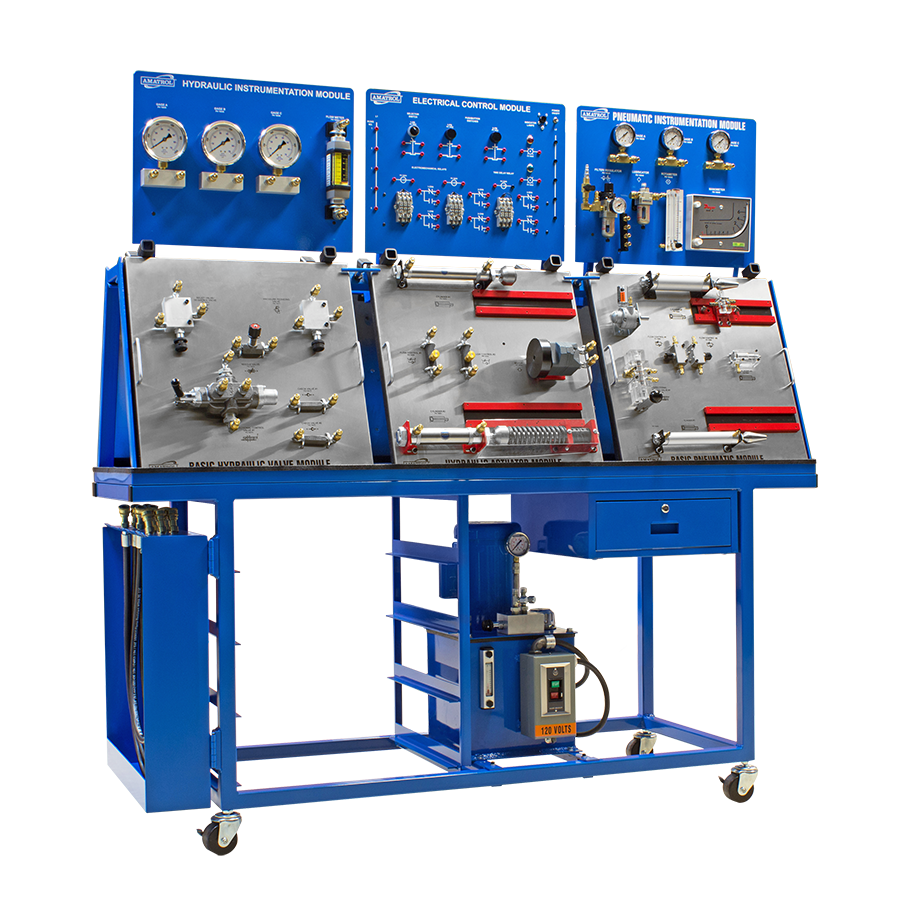
Basic Fluid Power Training System | Basic Pneumatics and Hydraulics

Microsoft Office Tutorials: Create a pneumatic or hydraulic control

Fluid power introduction

Hydraulic circuit of fluid power control system. | Download Scientific

1. Draw the circuit hose connections between circuit | Chegg.com

Figure 29 Typical Fluid Power Diagram